Pingxiang Volmet Import&Export Trading Co., Ltd. 萍乡市沃美特进出口贸易有限公司


TECHNICAL SPECIFICATION FOR VOL-1000/2 FOIL WINDING MACHINE
Short Description:
Contact Us
Video
1. GENERAL DESCRIPTION
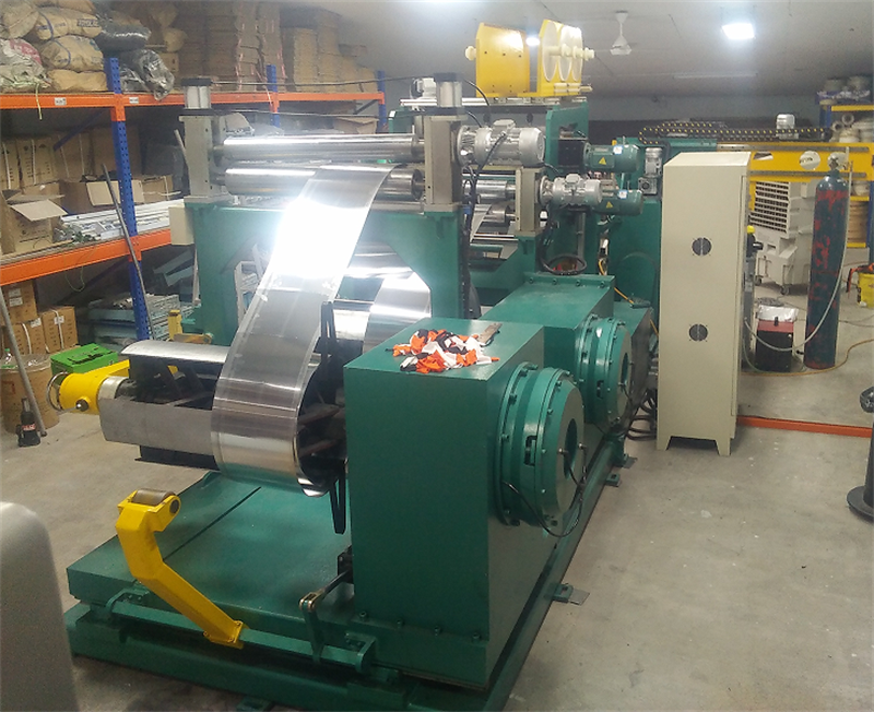
VOL -1000/2 Foil Winding Machine is the latest designed motor driven foil winding machine for winding the low voltage foil coil for transformer. It can wind cylindrical coils and rectangular coils.

2. THE FOIL WINDING MACHINE CONSISTS OF:
| Uncoiling device | 2 sets |
| Scissors device | 2 sets |
| Layer insulation uncoiling device | 2 sets |
| Welding unit (Including a TIG welder) | 1 set |
| Foil winding system | 1 set |
| End insulation device | 2 sets |
| Electrical control system | 1 set |
| Rectification device | 2 sets |
| Layer insulating cutting device | 1 set |
| Foil edge burr remover device | 2 sets |
| Foil edge clean device | 2 sets |
3.MAIN TECHNICAL PARAMETERS
3.1 Coil processing specifications
| Axial length (mm) | 350~1000 |
| Axial effective length(with terminal)mm | 1400 |
| Outer diameter of coil(with terminal)mm | Ø1100 |
| Outer diameter of coil (without terminal )mm | Ø900 |
| Min. Inner diameter of coil (mm) | Ø100 |
| Form of coil | Round, Rectangular |
| Material | Copper foil、Aluminum foil |
| Width range of coil (mm) | 350-1000 |
| Thickness of foil (mm) | Copper foil :0.3-2; Aluminum foil 0.5-3 |
| Coil inner diameter mm | ≤Ø500 |
| Coil outer diameter(Max)mm | Ø900 |
3.2 De-coiler specifications
| Effective length of roller mm | 1010 |
| Roller shrinkage range | Ø 460~ Ø 520 |
| Roller load(Max)kg | 2000 |
| Tension | 12000 N |
| Pressure | 0~0.6 Mpa |
| Rectify mode | Automatic, sensor system |
| Rectification precision (mm) | ±0.5 |
| Electronic control counting digits | Five(0-9999.9) |
3.3 Winding specifications
| Winding speed(speed stepless) | 0~30r/min |
| Working torque(Max) | ≥2000 N.M |
| Winding power (KW) | 15 |
| Speed adjusting mode | Frequency Stepless Speed Adjustment |
| Winding shaft length (mm) | 60*60*1550 |
3.4 Welding specifications
| Welding method | TIG Argon tungsten-arc welding (500A) |
| Welding corner | 0-60° |
| Welding speed (m/min) | Frequency Stepless Speed Adjustment 0-1 |
3.5 Scissors device
| Shear form | Screw rod cutting disc |
| Shearing speed | 1.5m/min |
| Sheared length (mm) | 1000 |
{Picture of layer insulation device}
{Picture of end insulation device}
3.6 Layer insulation
| Layer insulation installed shaft | 2 sets |
| Outer diameter of insulating paper (mm) | ≤Ø400 |
| Inner diameter of insulating paper (mm) | Ø76 |
| Width of insulating paper (mm) | 1050 |
| Installed axle | Pneumatic style |
3.7 End insulation
| Quantity | 2 sets |
| Outer diameter of end insulation (mm) | ≤ Ø350 |
| Inner diameter of end insulation (mm) | Ø56 |
| Width of end insulation (mm) | ≤50 |
3.8 Others
| Layer insulating cutting device | 1 set |
| Foil edge burr remover device | 2 sets |
| Foil edge clean device | 2 sets |
| 70*70 60*60 square shaft | Configure one piece (customize) |
| Transmission mode | Linkage、Manual |
| Operation mode | PLC control, touch screen operation;the man-machine interface |
4. TECHNICAL DESCRIPTION OF MAIN PART
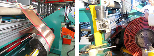
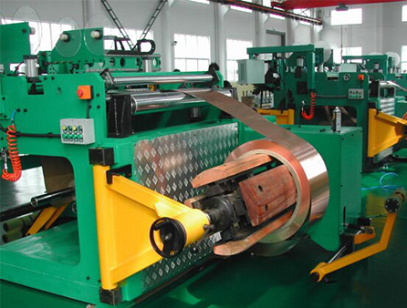
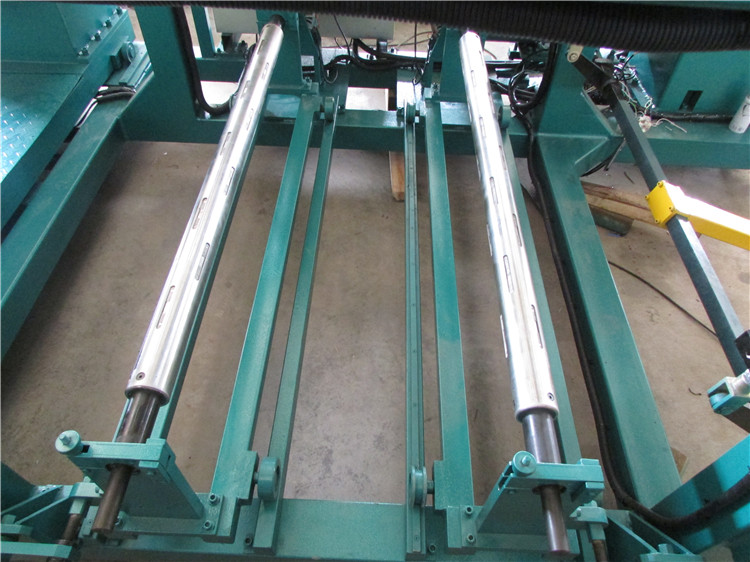
4.1 Uncoiling device
Including the uncoiling transmission case、pedestal、bracing plate、motor、rectification、 roller feed etc structure, as foil uncoiling device,have support material、uncoiling feeding、adjusting servo function etc.
Uncoiling device main shaft has square section,through three groups link rod support,coil can be hold tight on the roller. Main shaft can uncoil to feed and wind ,easy to adjust working condition.When linkage,through the clutch make shaft and actuating device to separate.Main shaft has press roller device,can independently or parallel use. Press roller adopt E-pneumatic, easy to control, clean safely.
Rectification adopt roller clutch,with the power system,According to the instructions of the PLC control system,uncoiling device will follow gib block move around quickly and accurately.In order to ensure the foil testing signal feedback of selvedge detector in the accurate position all the time,achieve the rectification function of foil.

{Picture of de-coiler device}
4.2 Layer insulation device:
Layer insulation device is to support the insulation material and make insulation generate tension during winding;
The device is consist of scroll, clutch, motor and controller.Convenience for feeding ,stent can be pulled out ;take down air swelling shaft,put on coil stock and push in ,make shaft end gear enter into damping device and then meshing,this moment, drive and damping function will act on insulation materials fixed on air swelling shaft. make layer insulation keep tension state in the process.the device have EPC control system,adopt hook ,through screw, using the hand wheel to conduct manual type rectification,simple structure, easy to operate.
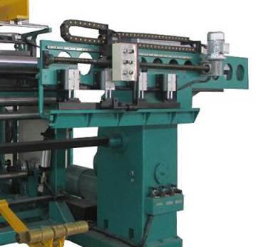
4.3 Welding device:
This welding device meet the foil tape and leading wire welding;Welding device installed on the winding transmission box, the welding arm can run around on the bedplate, after finishing the welding process, welding arm move back to the right, empty out the winding position, easy for winding operation;In order to adapt to lap welding, stud welding, butt welding, welding torch arm can make a large angle oscillation and the adjustment of the length, the welding torch clamp can customize according to the actual or be designed for replacement, welding torch device design several regulating function, can according to operating habits adjust at will.
Welding torch device installed on the straight line guide rail, through the motor (reducer), lead screw drive, can be adjusted to various position to adapt to the different forms of welding, using inverter infinitely adjustable-speed, can be very convenient to adjust welding speed.
{Picture of welding device}
4.4 Feeding device and deburring device:
This system consists of smooth roll shaft, feed roller, slide block device, driving system, foil via light roller, roller clamp foil tape by the cylinder ,remove burrs on the edge of the foil tape at the same time, the motor drive to achieve the purpose of feeding, cylinder lift stop feeding.
4.5 Detection edge device:
Adopt photoelectric selvage detector, responsive, high accuracy, can adjust with different width of the foil belt.
4.6 Dust removal device:
Fixed wool felt on square tube, pinned foil by air cylinder go upward and downward to remove dust, special governor valve to adjust air pressure based on actual needed.
4.7 Paper cutting axle:
This machine have paper cutting axle design., no dead angle.
4.8 Electric control system:
Adopts Japan Mitsubishi PLC system control, touch screen with button design, all programs (such as winding, correcting, turns controlling)will be counted by PLC control system, and send different instructions, then carry out the instructions by programs. The operator only need enter related parameters to finish mass production with same coil diameter. This machine can also operate manually by push buttons, such as jog and linkage, it also setting several emergency buttons on the main console and important console to stop machine on time when appear. emergency affairs. All operations of this system can be operated by main console.

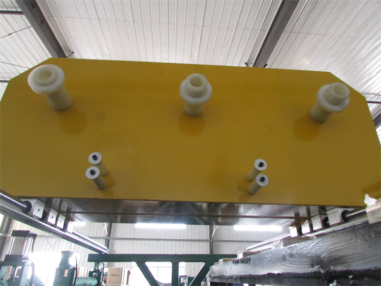
{Picture of distribution cabinet}
5. MAIN ELECTRICAL COMPONENTS
| PLC | Japan Mitsubishi |
| Touch screen | DELTA |
| AC vector converter | DELTA |
|
Low-voltage apparatus |
OMRON MEANWELL Taiwan SL |
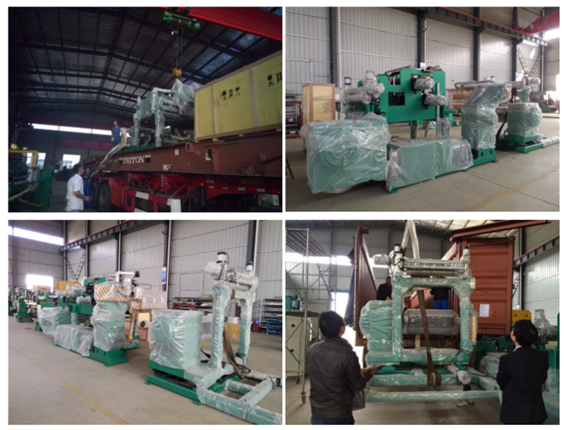
6.Transformer Foil Winding Machine Delivery And Package